Bode 100 & 500

Vektor Netzwerk Analyzer mit einem Frequenzbereich von 10 mHz bis 450 MHz

Für alle, die es ganz genau wissen wollen

Bode 100 & 500 liefern erstklassige Ergebnisse bei der Analyse von Schaltungen, Filtern & Netzteilen
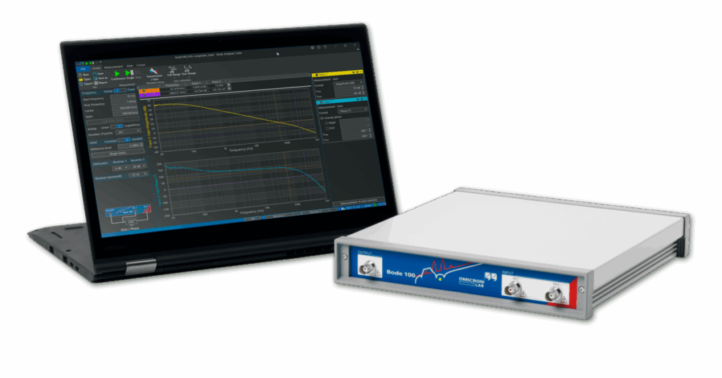
Die Bode 100 und Bode 500 von OMICRON Lab sind hochpräzise Vektor-Netzwerkanalysatoren, die entwickelt wurden, um elektronische Schaltungen und Komponenten über ein breites Frequenzspektrum zuverlässig zu charakterisieren. Diese multifunktionalen Messgeräte vereinen drei zentrale Analysefunktionen in einem kompakten Gerät:

1.

Vektor-Netzwerkanalyse (VNA)

Messen Sie S-Parameter (Streuparameter) wie Reflexion (S11) und Durchlass (S21) von passiven und aktiven elektronischen Bauteilen – von Filtern und Kabeln bis hin zu Antennen und Verstärkern.

2.

Frequenzgang-Analyse (Gain/Phase)

Erfassen Sie die Übertragungsfunktion von Schaltungen und Systemen, ideal zur Stabilitätsanalyse von Regelkreisen wie z. B. bei DC/DC-Wandlern oder Spannungsreglern.

3.

Impedanzanalyse

Bestimmen Sie die komplexe Impedanz von elektronischen Komponenten (Kondensatoren, Induktivitäten, Transformatoren, Piezo-Elementen etc.) über einen weiten Frequenzbereich hinweg – inklusive präziser Resonanzfrequenz- und Q-Faktor-Messungen.

Wann ist welches Modell geeignet?

Bode 100

Der Bode 100 ist damit die erste Wahl für Anwendungen, bei denen Präzision, Vielseitigkeit und ein exzellentes Preis-Leistungs-Verhältnis gefragt sind. Er ist die ideale Wahl für Forschung, Lehre und klassische Elektronikentwicklung. Mit seinem Frequenzbereich von 1 Hz bis 50 MHz, der intuitiven Software und dem lüfterlosen Design eignet er sich perfekt für präzise Standardmessungen in Laborumgebungen oder Ausbildungssettings.

Bode 500

Der Bode 500 erweitert den Frequenzbereich signifikant auf 10 mHz bis 450 MHz und bietet durch seinen hohen Dynamikbereich (>120 dB) sowie flexible Anschlüsse (USB-C, Ethernet, PoE) die ideale Lösung für moderne High-End-Anwendungen wie Power-Integrity-Analysen, Hochfrequenz-Tests und Netzwerkstabilitätsmessungen.

Beide Geräte sind vollständig in die benutzerfreundliche Bode Analyzer Suite integriert, die Ihnen eine intuitive Bedienung sowie umfangreiche Analyse- und Dokumentationsfunktionen bietet. Dank der Automatisierungsmöglichkeiten (z. B. SCPI, LabVIEW™) lassen sich die Analyzer problemlos in bestehende Test- und Fertigungsprozesse einbinden.

Zwei Lösungen – welche passt zu Ihnen?

Beide Modelle bieten zuverlässige Messergebnisse – je nach Frequenzbereich, Dynamikbedarf und Anwendungsschwerpunkt zeigt der Vergleich, welches Gerät besser zu Ihrem Projekt passt.

Top Anwendungen

Klicken Sie auf die Bilder, um mehr zu erfahren
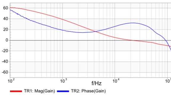
DC/DC Converter Stability Measurement

This application note explains how to analyze the control loop stability of DC/DC converters by measuring the loop gain. Electronic devices become smaller and smaller. Multiple supply voltage levels need to be maintained at very high converter efficiencies with fast recovery speed. Switching frequency tends to increase to make things smaller but also addy complexity to system models and design. In order to ensure the stability of voltage regulators and switched mode power supplies the control loop behavior needs to be characterized not only in simulation but also in real life measurements. The Bode 100 can easily be used to measure gain margin and phase margin of electronic control loops in a frequency range from 1 Hz to 50 MHz. Knowing your system gain margin and phase margin gives you the certainty that your system will be stable even under changed circumstances. To learn how to use the Bode 100 to measure the loop gain of a buck converter, please download the applcation note:

Impedance Measurements using the Bode 100

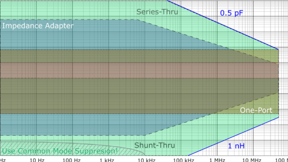
This application note discusses how to choose the correct impedance measurement method when measuring impedance using the Bode 100 and how to improve results. The Bode 100 offers seven different impedance measurement methods to measure impedance values from mΩ to MΩ over a wide frequency range from 1 Hz to 50 MHz. The simplest measurement possibilities are the one-port measurement or the impedance-adapter method. If these “simple” measurement possibilities are not good enough (e.g. to measure in the µΩ or mΩ range, the high variety of impedance measurement possibilities allows to choose the optimal setup for your application. Using calibration / correction, the influence of the test setup including possible amplifiers or attenuators can be compensated for. Using special measurement modes, even the impedance of active devices such as switching power supplies or power delivery networks can be measured. Check out the application note or the related information to learn more about the impedance measurement capabilities of your Bode 100.

Output Impedance of Power Supplies

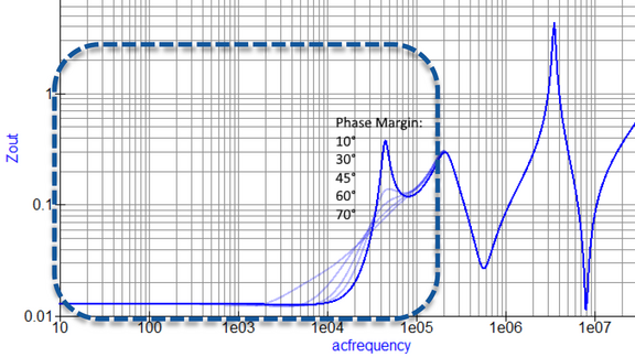
In this application note, we show how to measure the output impedance of DC/DC converters or voltage regulators and how to use this information to derive the phase margin and select the right decoupling network. The output impedance of a voltage regulator or DC/DC converter contains information about the control-loop stability as well as information about the decoupling network. The theory behind the Non-Invasive Stability Measurement (NISM) is explaind and verified based on a lab-experiment on a SEPIC converter. If you want to know more about why measuring the ouptut impedance of a DC/DC converter can support your design process, please check out the following application note:

Input Impedance & Filter Stability

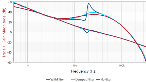
In this application note, we show how the Bode 100 can be used to measure the input impedance of a DC/DC converter and why this is important for system stability. In this application note, we are reviewing the theory behind the input filter stability problem. Why the input filter of a DC/DC converter can cause converter instability and how the negative input impedance of the converter contributes to this. Various impedance measurement setups for mW to kW converter applications are discussed and the settings details of Bode Analyzer Suite are explained. Based on a lab-experiment a bad input filter design is measured and the impact on the loop gain as well as on the transient response is analyzed. Successful filter damping reduces the input filter problem but still provides the advantage of a filtered input signal. If you want to know more about why the input filter of a DC/DC converter can lead to converter instability and how you can measure input impedance using the Bode 100, please download the following application note:

Traditional and Non-Invasive Stability Measurement

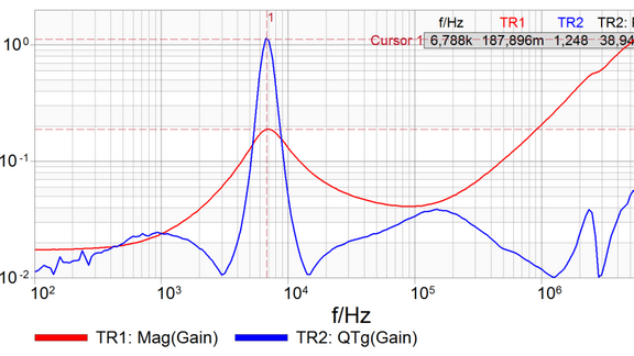
Sometimes you have no access to the feedback loop of a voltage regulator. This application note shows how you can measure the stability in such cases non-invasively. The stability of voltage regulators is a very important parameter in electronic systems. Unexpected ringing due to load changes can affect the whole system performance. Measuring the phase margin of the feedback system helps to evaluate the stability and uncovers critical resonances. In some cases the feedback loop of the voltage regulator is not accessible from outside. The Bode 100 in combination with the Picotest J2111A current injector enables you to measure the output impedance of the system and to determine the phase margin of the system without breaking the feedback loop. As a result you are able to perform a Non-Invasive Stability Measurement (NISM). We have performed the measurements on the Picotest VRTS 1.5 and the VRTS 2 board. The VRTS 1.5 board contains a floating regulator whereas the VRTS 2 board features a ground-based regulator circuit. Please download the corresponding application note describing first the traditional loop gain measurement and second an output impedance measurement where we apply NISM:

Power Supply Rejection Ratio Measurement

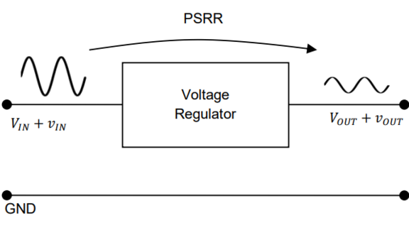
The PSRR is an important quality indicator for power supplies. It can be easily measured with the Bode 100 and the Picotest J2120A Line Injector. This Application Note shows how. R&D engineers for power supplies are often challenged to measure Power Supply Rejection Ratio or Power Supply Ripple Rejection (PSRR). The PSRR is a very important parameter for power stability. It provides information on the influence of input voltage variations on the stability of the output voltage. Measuring PSRR requires a high dynamic range of the measurement equipment. Therefore it was so far quite seldom measured. The Bode 100 and the Picotes J2120A Line Injector enable a simple, reproducible and exact measurement of the PSRR. Good power supplies can reach a supply voltage ripple rejection of more than -100 dB. In our application note we describe step-by-step how you can easily measure the PSRR in your lab environment. Besides the correct setup of the Bode 100 it is shown how the output capacitor influences the PSRR and power stability. To find out more on this measurement approach and the according background just download the application note below:

Möchten Sie unsere Beratung?​

Melden Sie sich telefonisch oder per E-Mail mit ihrem Anliegen und wir kümmern uns darum, so bald wie möglich!

Nach oben scrollen
Datenschutz-Übersicht

Auf dieser Website werden Cookies u.a. für Werbezwecke, Zwecke in Verbindung mit Social Media sowie für analytische Zwecke eingesetzt. Wenn Sie weiter auf der Website surfen, erklären Sie sich mit dem Einsatz von Cookies einverstanden. Klicken Sie auf "Alle Ablehnen", um die Verwendung von Cookies von Drittanbietern abzulehnen.

Zur vollständigen Datenschutzerklärung.